| Row # |
Title |
Image |
Description |
| 1 |
EAGLE PCB Software |
 |
A PCB design software by CadSoft. EAGLE stands for Easily Applicable Graphical Layout Editor. |
| 2 |
AutoCAD Electrical
|
|
CAD software for electrical design.
|
| 3 |
KiCad
|
 |
KiCad is a free EDA (electronic design automation) software suite for the creation of professional schematics and printed circuit boards of up to 16 layers.
|
| 4 |
Pcschematic Automation
|
|
Electrical CAD software for drawing schematics, electrical wiring diagrams, control circuit diagrams, pneumatics and hydraulics.
|
| 5 |
XCircuit
|
 |
A free program for drawing publishable quality electrical circuit schematic diagrams and related figures, and produce circuit netlists through schematic capture.
|
| 6 |
GeckoCIRCUITS
|
|
GeckoCIRCUITS is a free circuit simulator for modelling power electronics systems.
|
| 7 |
GeckoMAGNETICS
|
 |
GeckoMAGNETICS is a software tool for the modelling and optimal design of inductive power components, such as inductors and transformers. It works for a wide power range, for all type of core materials, and many winding types (including Litz and foil windings). It can also be linked to the free circuit simulator GeckoCIRCUITS.
|
| 8 |
GeckoEMC
|
 |
GeckoEMC is a 3D CAD Partial Element Equivalent Circuit (PEEC)-based virtual prototyping platform, that enables a highly accurate and fast prediction of the electromagnetic behaviour of power converter systems and their components. It facilitates the electromagnetic modelling of PCB layouts, bus bars, power modules, EMI filters structures etc., in time and frequency domain. Unlike many other similar PEEC-based simulation tools, GeckoEMC allows the possibility of frequency domain modelling of magnetic inductors built with toroidal cores. This enables 3D modelling of full EMI filter circuits including all parasitic effects. GeckoEMC links to the circuit simulator GeckoCIRCUITS.
|
| 9 |
GeckoHEAT |
|
GeckoHEAT is a tool (currently in development) for the thermal modelling of components in power electronic systems. It can be linked to the circuit simulator GeckoCIRCUITS. |
| 10 |
Atlence Resistor Viewer
|
|
Atlence Resistor Viewer is a program that can be used to get the value and characteristics of a resistor from its colour bands and vice versa.
|
| 11 |
Schematica - Resistor Color Coder |
 |
A program for determining resistor colour bands from value, or value from colour bands. It works for both 4 and 5 colour band resistors.
|
| 12 |
Schematica - eSketch
|
 |
A powerful schematic capture and simulation application designed specifically for the ultra-fast rendition and simulation of frequency-shaping analog circuits.
|
| 13 |
Schematica - Filter Wiz Lite
|
 |
A free, eSketch compatible, active filter designer with 5 approximations (including elliptic) and 32 circuit topologies.
|
| 14 |
Schematica - Filter Wiz PRO
|
 |
An advanced, eSketch compatible, active filter designer with over 20 approximations, 79 circuit topologies, built-in analog simulator and design aids.
|
| 15 |
Schematica - 555 Timer Free
|
 |
A free 555 timer with 3 astable modes, monostable (one-shot) mode, duty cycle indicator, and can tweak R & C values.
|
| 16 |
Schematica - 555 Timer PRO |
 |
Software with design wizards, circuit blocks and information panels that facilitate the use of the 555 timer in projects. The component value calculations for the 555 take into account the supply voltage, timer fabrication (CMOS or Bipolar), and where appropriate, load currents.
|
| 17 |
Schematica - 555 Timer PRO EX
|
 |
555 Timer PRO EX has all the features of 555 Timer PRO, plus wizards for active filter design, photodiode amplifiers, op amp amplifiers and transistor amplifiers.
|
| 18 |
Schematica - Op Amp Selector |
 |
A Windows application that incorporates an up-to-date database of over 500 voltage feedback operational amplifiers, each of which has been indicated by the manufacturer as being suitable for use in active filtering. |
| 19 |
RnD Warehouse - LM317 Voltage Regulator Calculator |
|
A free electronic engineering calculator to determine resistor values and voltage outputs for the common LM317 programmable voltage regulator.
|
| 20 |
TinyCAD
|
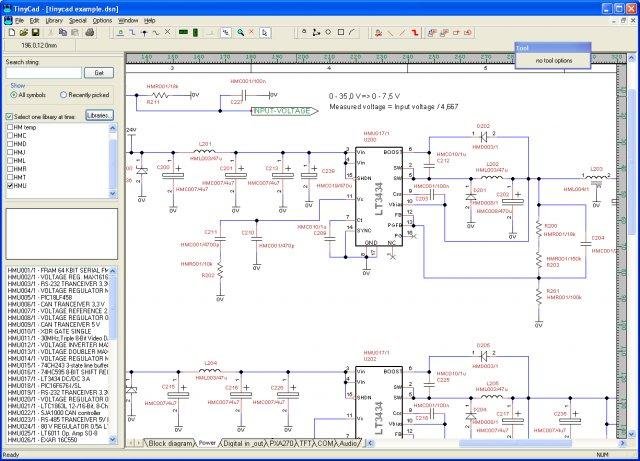 |
TinyCAD is a free program for drawing electrical circuit diagrams (commonly known as schematic drawings). It supports standard and custom symbol libraries. It supports PCB layout programs with several netlist formats and can produce SPICE simulation netlists. It can also be used to draw one-line diagrams, block diagrams, and presentation drawings.
|
| 21 |
VeSys Design
|
|
VeSys Design is a graphical authoring environment for creating vehicle wiring diagrams.
|
| 22 |
5Spice
|
 |
Analog circuit simulation software with a focus on analysis and design at the component level. It allows Spice specific schematic entry, the ability to define and save an unlimited number of analyses, integrated graphing of simulation results, and easy inclusion of Spice/PSpice models from a user expandable library. The focus is on analog circuit analysis and design at the component level.
|
| 23 |
Edraw Max
|
|
Diagram drawing software with features designed for drawing electrical diagrams.
|
| 24 |
Elecdes Design Suite
|
|
Electrical engineering software for electrical CAD. |
| 25 |
EasyPower
|
|
Arc flash hazard analysis software
|
| 26 |
PowerStar Electrical
|
|
Electrical engineering software with the following features:
- Draw and print single line diagrams.
- Displays complete device information including node voltages, voltage drops, current, kW, kVA and kVAr flow.
- Evaluate the effects of disconnected devices and branches on the rest of the circuit.
- Calculate three-phase, line-to-neutral and line-to-line load flow.
- Click on a symbol to display or edit device rating and other properties.
- Mouse-over any symbol to display electrical data.
- Highlight devices with overcurrent, kVA/kW overload, or over/undervoltage.
- Print or plot to any Windows compatible printer or plotter.
- Circuit report format compatible with MS Word, OpenOffice, and Mac.
- Use graphics to annotate and add legends, title blocks, and logos to a single line diagram.
|
| 27 |
PowerNet Circuit Analyzer
|
|
Electrical engineering software with the following features:
- Draw and print single line diagrams.
- Displays complete device information including node voltages, voltage drops, branch current, kW, kVA and kVAr flow.
- Evaluate the effects of disconnected devices and branches on the rest of the circuit.
- Calculate three-phase, line-to-ground, line-to-line and double line-to-ground fault. Include motor contribution to fault. Shows earth current, fault R/X ratio, RMS and peak fault current.
- Mouse-over display of device electrical data.
- Mouse-over display of voltage and current vectors.
- Create or modify device symbols.
- Highlight devices with overcurrent, kVA/kW overload, over/undervoltage.
- Print or plot to any Windows compatible printer or plotter.
- Use graphics to annotate and add legends, title blocks, and logos to a single line diagram.
- Circuit report format compatible with MS Word, OpenOffice, and Mac.
|
| 28 |
PowerVue Circuit Analyzer
|
|
Electrical engineering software with the following features:
- Draw and print single line diagrams.
- Calculate voltage drops and branch currents.
- Analyse DC, single phase or three phase circuits.
- Display complete device information including node voltages, voltage drops, current, kW, kVA and kVAr flow.
- Evaluate the effects of disconnected devices and branches on the rest of the circuit.
- Calculate three-phase, line-to-ground, line-to-line and double line-to-ground fault. Include motor contribution to fault. Show earth current, fault R/X ratio, RMS and peak fault current.
- Display voltage and current vectors.
- Add to or modify database device classifications, and add or modify device database records.
- Highlight devices with overcurrent, kVA/kW overload, or over/undervoltage.
- Use graphics to annotate and add legends, title blocks, and logos to a single line diagram.
|
| 29 |
Qucs
|
|
Qucs stands for Quite Universal Circuit Simulator. The software can be used to setup a circuit with a graphical user interface (GUI), and simulate the large-signal, small-signal and noise behaviour of the circuit.
|
| 30 |
AKNM Circuit Magic
|
 |
An electrical circuits simulation program designed for students learning basic electronics, electrical laws, and circuit theory. Its schematics editor allows the user to construct electrical circuit schematics consisting of direct and alternating currents, and devices such as resistors, capacitors, inductors, impedances, DC voltage sources, DC current sources, AC voltage sources, and AC current sources. It also allows the analysis of basic electronic circuits using Kirchhoff's Laws, node voltage, and mesh currents methods.
|
| 31 |
TopSpice
|
|
An analog/digital/behavioral mixed-mode circuit simulator for the PC.
|
| 32 |
Spice Opus
|
|
A free general purpose circuit simulator suited for optimisation loops.
|
| 33 |
CircuitPlusPlus
|
|
A simulator for analog and digital circuits based on Falstad's Circuit.
|
| 34 |
AIM-Spice |
|
AIM-Spice stands for Automatic Integrated Circuit Modeling Spice, and is a version of SPICE (Simulation Program with Integrated Circuit Emphasis). |
| 35 |
ETAP Software |
 |
ETAP® is a full spectrum analytical engineering software company specializing in the analysis, simulation, monitoring, control, optimization, and automation of electrical power systems. ETAP electrical engineering software offers a comprehensive suite of integrated power system enterprise solutions. |


